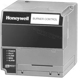
Honeywell RM7895B1013/U — Автоматы управления горелками серии 7800
Honeywell · Артикул: RM7895B1013/U
Описание
Honeywell RM7895B1013/U — Автоматы управления горелками серии 7800. Артикул производителя: RM7895B1013/U. Раздел каталога: Автоматы управления горелками серии 7800. Характеристики исполнения: Напряжение — 120 Vac (+10, -15%); Тип запальной горелки — intermittent; AirFlow Check — Dynamic; Delayed Main Valve — Нет; Время установления пламени основной горелки — Intermittent; Время установления пламени запальной горелки — 4 to 10 sec.
Характеристики исполнения
- Напряжение
- 120 Vac (+10, -15%)
- Тип запальной горелки
- intermittent
- AirFlow Check
- Dynamic
- Delayed Main Valve
- Нет
- Время установления пламени основной горелки
- Intermittent
- Время установления пламени запальной горелки
- 4 to 10 sec
- Approvals, Underwriters Laboratories Inc.
- YES
- Approvals, CSA
- YES
- Approvals, Factory Mutual
- YES
- Acceptable: Control Safety; CSD-1
- YES
Документация
Состав и замены
Подбор замены для семейства: таблица 7800 Series
Таблица относится к семействам. Точный артикул, усилитель, основание Q7800A, таймер и изменения подключения подбираются по условиям производителя. Полная инструкция сохранена ниже.
| Honeywell Device to be Replaced | Replace With | Amplifier |
| RA890E, F | RM7895A | R7847A |
| RA890G | RM7895A | R7849A |
| R4795A, D/W-R7290 AMP | RM7895A | |
| R4795A, D/W-R7289 AMP | RM7895B | R7847A |
| R7795A | RM7895A | R7849 |
| R7795B | RM7895A | R7847 |
| R7795C | RM7895C | R7849 |
| R7796D | RM7895C | R7847 |
| R4140P | RM7895C | R7847A or R7849A |
| R4140Y | RM7895A | |
| Fireye Device to be Replaced | Replace With | Amplifier |
| TFM1, 2, 3H | RM7895A | R7847A |
| UVM1, 2, 3, 3H | R7849A | |
| UVM5 | RM7895C | R7849A |
Полные условия изготовителя
7800 Series Product Selection for legacy and competitor replacements 7800 Series Product Selection for legacy and competitor replacements Honeywell Device to be Replaced Replace With Amplifier RA890E, F RM7895A R7847A RA890G RM7895A R7849A R4795A, D/W-R7290 AMP RM7895A R4795A, D/W-R7289 AMP RM7895B R7847A R7795A RM7895A R7849 R7795B RM7895A R7847 R7795C RM7895C R7849 R7796D RM7895C R7847 R4140P RM7895C R7847A or R7849A R4140Y RM7895A Fireye Device to be Replaced Replace With Amplifier TFM1, 2, 3H RM7895A R7847A UVM1, 2, 3, 3H R7849A UVM5 RM7895C R7849A IMPORTANT: For on-off, gas-fired systems, some authorities having jurisdiction prohibit the wiring of any limit or operating contacts in series with the main fuel valve(s). CONVERSION CHART FOR RM7895 120 VOLT ONLY Q7800 TERMINAL L1 L2 3 4 6 7 8 9 10 21 F G Programmer to be Converted RA890 (All) 1a 2 c b, d 6 b 3d 5 4 — F G R4795 (All) a 2 c 8, 7 1 6b 3 5 4 — F G R7795A, B L1 L2 9 8 16 3 5 6 18 — F G R7795C, D L1 L2 9 8 16 3 5 6 18 7 F G R4140P L1 L2 A M 3 P 5 7 — 6 S1 S2 R4140Y L1 L2 9 8 4 3 6 7 5 — Fe G Fireye: UVM/TFM (All models)/MII 1 1 A 8 7 6 3 5 4 — S2f S1 UVM-1 (Prior to 1968) a 2 A b, d 1 b 3 5 4 — Sf S UVM-2 (Prior to 1968), All others a 2 A 8 1 6 3 5 4 — Sf S a Connect power to terminal L1. b If no airflow switch is used, jumper Q7800 terminal 6 to 7. c Replace low voltage alarm (if used) with line voltage alarm. Connect alarm directly to Q7800 terminal 3. d On power burners, identify burner motor wire on terminal 3 and connect it to Q7800 terminal 4. e Select amplifier to match detector being used. f On UVM models, the detector must be changed to a Honeywell C7027 or C7035. REPLACEMENT DIRECTIONS: 1. Disconnect all power to programmer. 2. Remove old programmer from subbase (trade-in to Honeywell Authorized Flame Safeguard Distributor). 3. Mark all wires on subbase; i.e., wires connected to terminal “1” should be marked “1.” Disconnect wires as they are marked. 4. Remove old subbase. 5. Mount Q7800A Subbase. 6. Connect wires to subbase per attached cross reference. Pay close attention to footnotes. For example: to convert a Fireye UVM-2 to a RM7895, the wire marked “A” would connect to terminal #9 on the Q7800. The wire marked “8” would connect to Q7800 terminal #8. 7. A superscript letter, such as “a” designates a footnote. Study these footnotes carefully. 8. Plug in the RM7895. Make sure you select the proper ST7800A Purge Timer and Detector for the application. 9. There are 2 wires on the amplifier section of the RM7895, which are used to select the desired trial for ignition timing and mode (lock-out or recycle). Refer to the RM7895 instruction sheet (form 66-1090) for assistance with proper selection. 10. If a low voltage controller is used on the RA890 or UVM-1, remove it and replace it with a line voltage controller. The line voltage controller should be connected in series with the limits. 11. If a low voltage airflow switch is used on the RM7895, it must be replaced with a line voltage airflow switch. 12. The following models are recommended for replacements: 70-8911 19
Honeywell · Kromschroder · Resideo
ООО «Промэлектроника» · 8 800 333-19-98 · sales@prom-elec.com